Engineering drawings follow regional and industry standards: ISO internationally, ASME (often called ANSI) in the United States, DIN in Germany, JIS in Japan and BS 8888 in the United Kingdom. Your CAD drawings need to be set up to match the one your customer needs.
Let's look at the major engineering drawing standards, what they cover and how you can work with them in Octave BricsCAD. For a side-by-side summary, see the “standards at a glance” table on our engineering drawing software page.
Which engineering drawing standard should you use?
ISO: International engineering drawing standards
The International Organization for Standardization (ISO) develops standards used by engineering and manufacturing industries worldwide. Rather than a single standard governing every aspect of a drawing, ISO drawing standards are a series of standards covering different elements of technical documentation. For example, ISO 128 addresses technical drawing representation, while ISO 129-1 covers dimensioning.
ANSI/ASME: Engineering drawing standards in the US
In the US, engineering drawings commonly follow the ASME Y14 series, developed by the American Society of Mechanical Engineers. One of the most important is ASME Y14.5, which establishes rules for geometric dimensioning and tolerancing (GD&T).
DIN: German engineering drawing standards
DIN drawing standards are developed by the German Institute for Standardization. Many German drawing standards adopt European and international requirements. Editions matter. For example, many drawings still give general geometrical tolerances according to DIN ISO 2768-2. That standard has been withdrawn and replaced by DIN EN ISO 22081. DIN ISO 2768-1, which covers general tolerances for linear and angular dimensions, still applies.
JIS: Japanese Industrial Standards
Japanese Industrial Standards (JIS) are Japan’s national technical drawing standards for engineering and manufacturing. JIS Z 8310 sets out general drafting practices, while JIS B 0001 covers mechanical engineering drawings, including part and assembly drawings.
One key difference from ISO is projection method. Japanese drawing standards generally specify third-angle projection for mechanical drawings, while ISO-based drawings in Europe usually use first-angle projection. An existing ISO drawing template may therefore not suit a Japanese customer without changes.
BS 8888: Engineering drawing standards in the UK
BS 8888 is the UK's national standard for technical product specification and documentation, published by the British Standards Institution (BSI). It brings together requirements from international ISO standards and provides a framework for documenting products and their components. The current edition, BS 8888:2025, also includes updated guidance on model-based definition and geometrical tolerancing.
What are the main differences between engineering drawing standards?
When working with drawings from different countries or suppliers, confirm which standard and edition the customer specifies before you start. Here are some of the main areas to check.
First-angle and third-angle projection
First-angle projection is commonly used in Europe and many international markets, while third-angle projection is common in the US, Canada and Japan. In first-angle projection, the right-side view is placed to the left of the front view. In third-angle projection, the right-side view appears on the right.
Dimensions and tolerances
ISO and ASME standards provide rules for geometric dimensioning and tolerancing, but the two systems aren't always interchangeable. For example, a geometric tolerance symbol may have different default interpretations under ISO and ASME rules. A drawing prepared using one system shouldn't automatically be interpreted using the other.
Line types, symbols and annotations
Visible edges, hidden features, centerlines and section views are represented using established line and symbol conventions. Standards also address how dimensions, notes and other annotations should appear on a drawing. They set line weights, so visible outlines appear thicker than hidden or center lines. Lettering style and minimum text height are also defined.
Engineering drawing title blocks and drawing information
An engineering drawing title block typically identifies the drawing, its revision, scale and responsible organization. It provides a consistent place for essential drawing information, making it easier for anyone reviewing the drawing to identify the correct document and version. The precise requirements for an engineering drawing title block depend on the applicable standard and the organization's own documentation practices.
How can you work with engineering drawing standards in BricsCAD?
BricsCAD provides drawing templates, styles and CAD Standards tools to help you set up drawings and maintain consistent drawing properties.
Set up and check your drawing
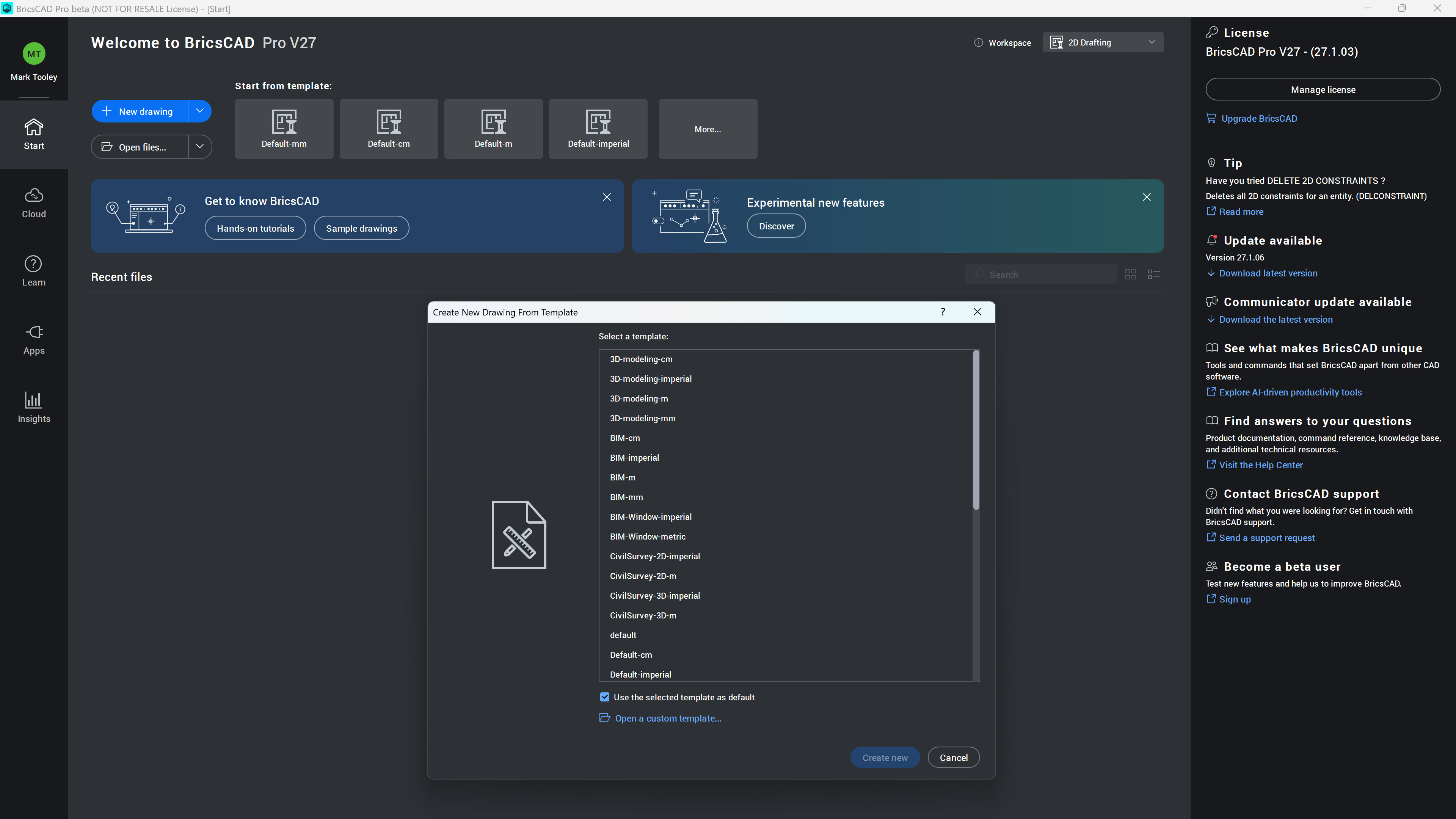
1. Start with a drawing template
Open a drawing template (DWT) and configure it to meet your project’s requirements.
For mechanical drawings, the BricsCAD Mechanical toolset also includes drafting standard settings for ISO, DIN, JIS and ANSI, which you can apply using the AMSETUPDWG command.
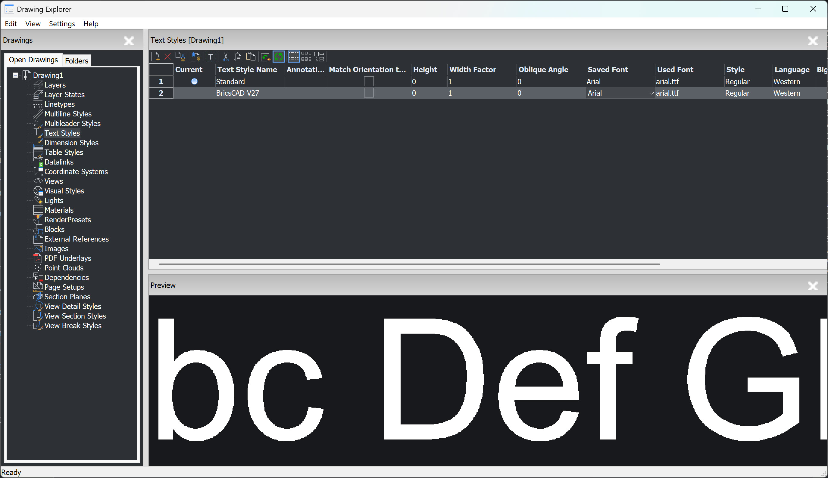
2. Configure dimension and text styles
Set up your dimension and text styles to match the applicable drawing requirements.
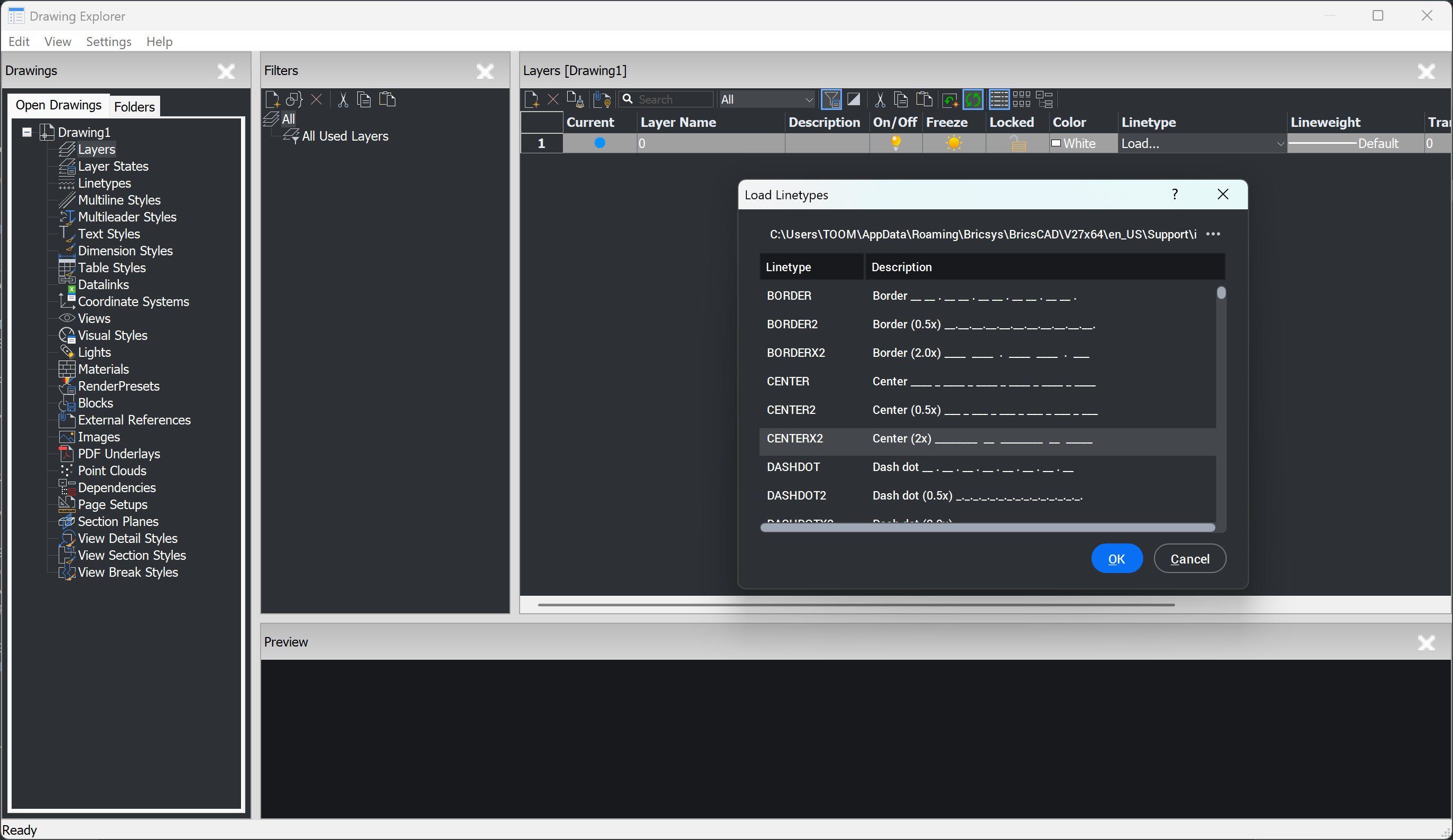
3. Set up layers and linetypes
Configure your layers and linetypes, including the conventions used for visible edges, hidden features and centerlines.
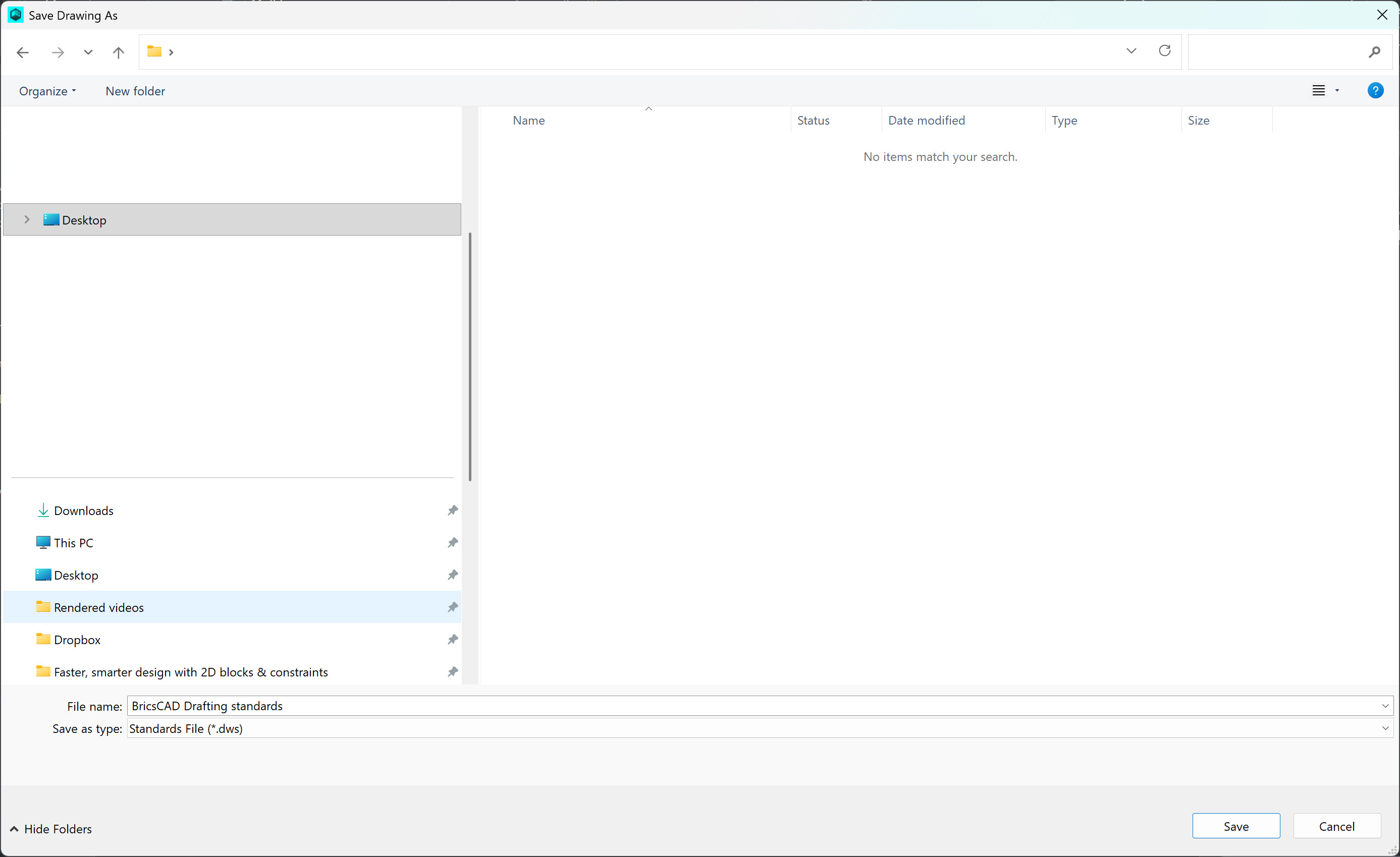
4. Save a standards file
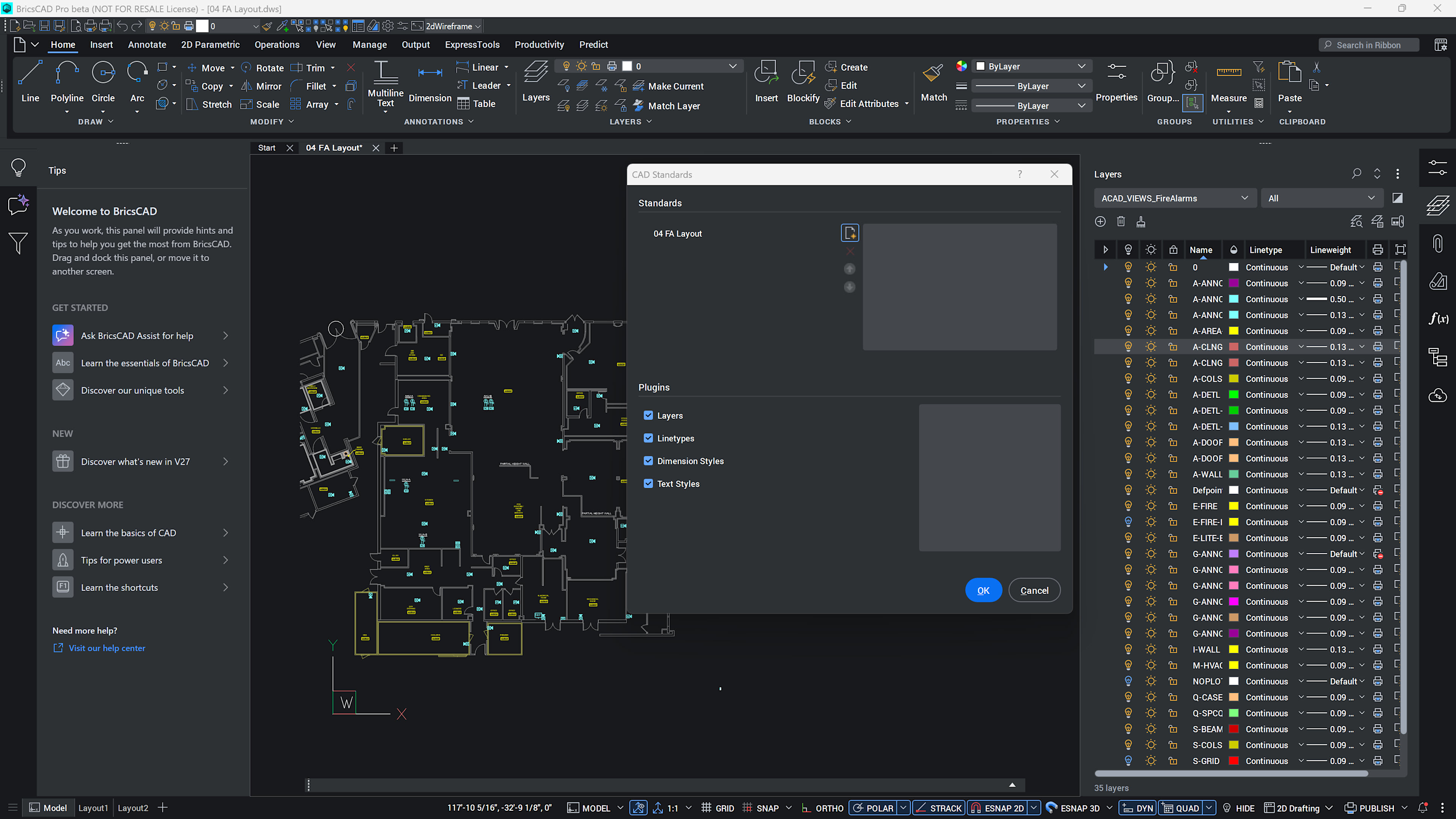
Use SAVEAS and select the DWS file format to save your drawing properties as a CAD Standards file.
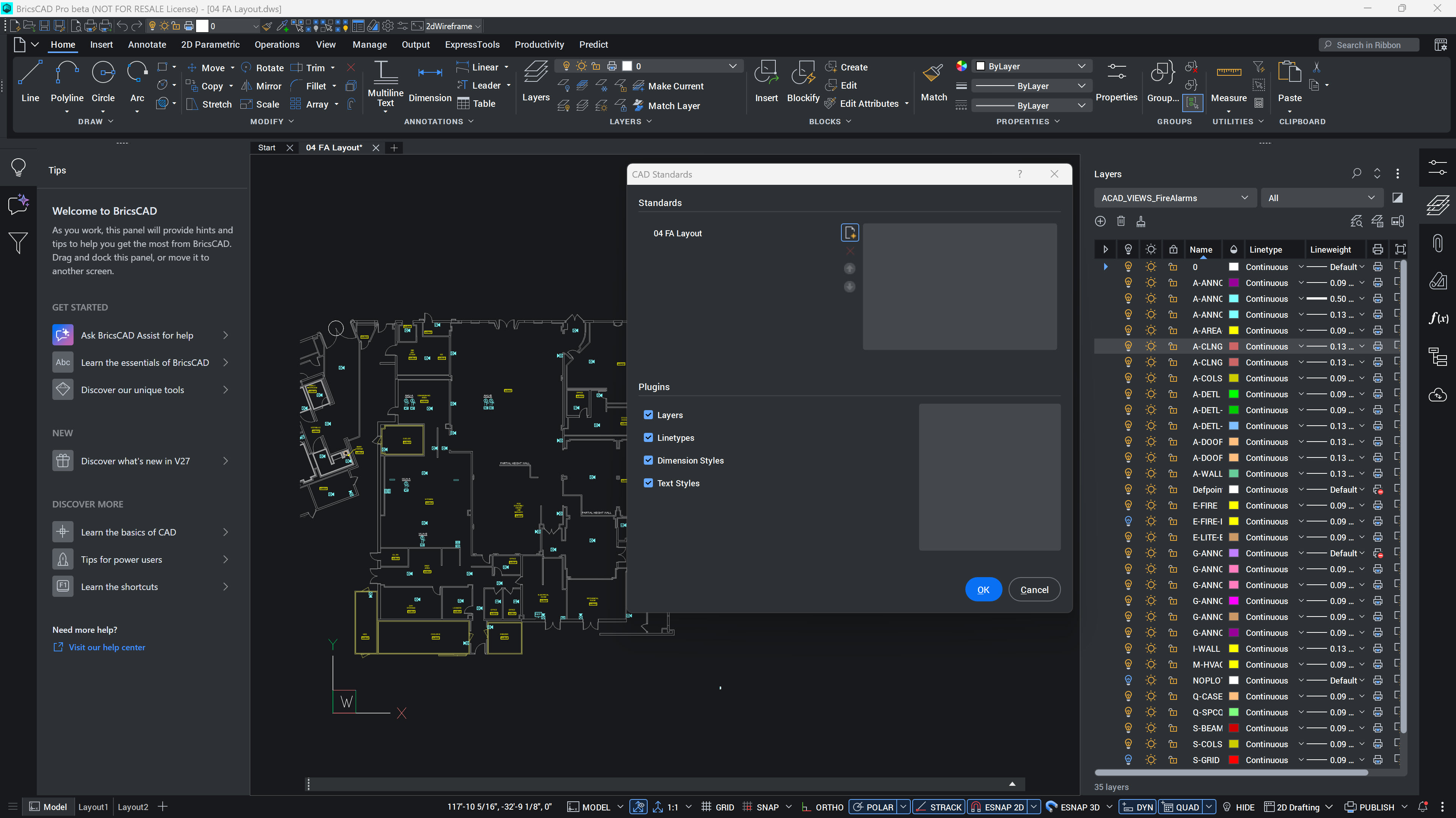
5. Associate the standards file with your drawing
Use the STANDARDS command to associate your DWS file with the drawing you want to check.
6. Check your drawing for inconsistencies
Run CHECKSTANDARDS to compare the drawing's layers, linetypes, dimension styles and text styles against the associated DWS file. Review any differences and make corrections where needed.
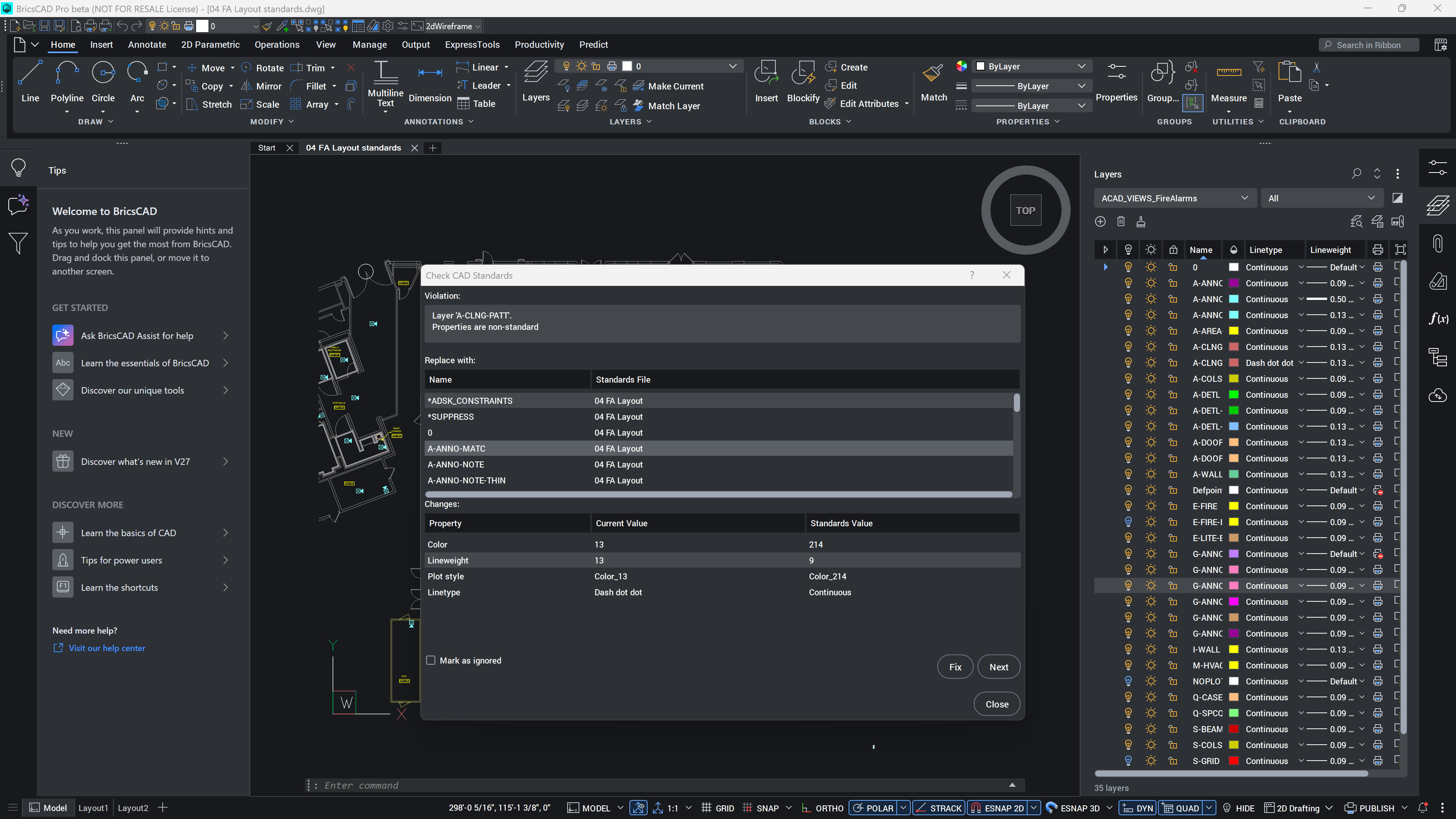
The STANDARDS and CHECKSTANDARDS commands are available in BricsCAD Lite, Pro, Mechanical and BIM. For checking multiple drawings, BricsCAD V27 also includes a standalone CAD Standards validation application, available on Windows and macOS.
These tools help you maintain consistent drawing settings, although they don't replace a full review against the requirements of the applicable engineering drawing standard.
Learn more about the available tools on our 2D drafting page.
What about engineering drawings created from 3D models?
Engineering documentation often involves generating 2D drawings from existing 3D models. In BricsCAD Pro, Mechanical and BIM, the VIEWBASE command creates orthographic and isometric drawing views from 3D solids. You can use the PROJECTIONTYPE variable to select first-angle or third-angle projection to control how the views are arranged.
For an example of this workflow, see our tutorial on creating orthographic drawings from a 3D model.
Frequently asked questions about engineering drawing standards
Are ISO and ANSI drawing standards the same?
No. ISO standards are developed for international use, while engineering drawings in the United States commonly follow the ASME Y14 series. Although both address the presentation of technical information, certain conventions and requirements differ, particularly in geometric dimensioning and tolerancing.
Is BS 8888 the same as ISO?
BS 8888 draws together international ISO standards within a UK framework for technical product specification and documentation. It references multiple ISO standards rather than replacing them with one separate set of drawing rules.
Can BricsCAD check a drawing against a standard?
Yes, for drawing properties. You can save layers, linetypes, dimension styles and text styles in a CAD Standards (DWS) file. Then run CHECKSTANDARDS to find and fix differences in any drawing. It doesn’t check whether the drawing meets every requirement of a standard, so a technical review is still needed.
Keep your engineering drawings consistent
Start by confirming which standard and edition your customer specifies. Then build a template that reflects it and check your drawings against a CAD Standards file to keep layers and styles consistent across your team.
Octave BricsCAD provides tools for creating and managing engineering drawings in a native DWG environment. Explore our engineering drawing software or try BricsCAD free for 30 days.