Flexible 3D modeling tools
Visualize and create detailed 3D models with an intelligent toolset to share and validate design intent.
3D COMPONENT DESIGN
Powerful 3D modeling tools leveraging 2D data
Work smartly with parametric and direct modeling in BricsCAD for precise control and freedom to design.
3D visualization, 2D output
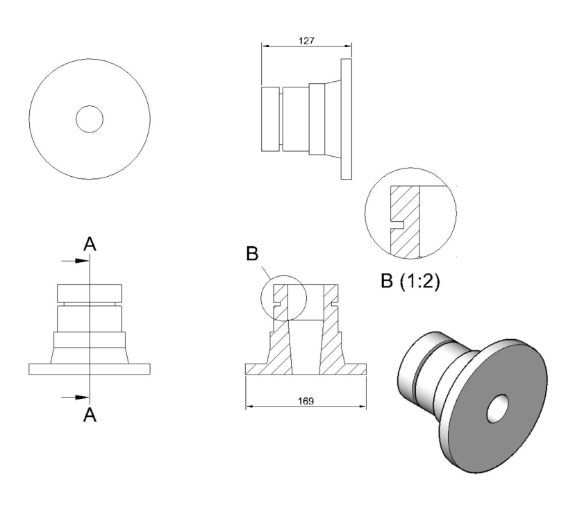
Leverage 2D data and create 3D Solid geometry from 2D cross-sections to check for interferences/clearances. Use the solid geometry to build component details and take cross-sectional views for calculations in 2D drawings.
Edit 3D geometry and create production data
Compelling visualization with 3rd party apps
FAST MODELING FROM 2D
Build 3D from 2D DWG files or directly edit components
Accelerate 3D model creation in BricsCAD with several options. Import 2D profiles from existing DWG files to create 3D geometry. Alternatively, create 2D profiles to convert into solid geometry using sketch-based features. Predefined shapes can be created quickly and manipulated with direct editing tools.

3D geometry from primitive shapes
Predefined 3D solids act as a building block for creating solid geometry. Used with direct modeling tools, users can easily modify them to quickly develop design concepts.

Sketch Based Features
Create complex 3D solids for concept visualization, using standard 3D commands. Feature parameters enable users to quickly edit the design and get instant updates to linked documents.

Direct editing for solid geometry
Modify imported solid geometry with powerful direct editing commands. The common editing tools allow users to add or remove material from solid or surface bodies to show design intent.
FAMILIAR 3D COMMANDS
Create 3D geometry quickly with industry-standard commands
BricsCAD’s modeling tools allow users to generate 2D deliverables quickly within a single DWG environment using intuitive and familiar modeling commands.

Convert 2D DWG into solids
Use imported or existing BricsCAD 2D data to create 3D solid components with standard, editable feature commands.

Surfaces and splines
Create complex surfaces and curvatures and use Splines to create free-form shapes and lines in a 3D space.

Manipulate 3D entities
Modify 3D objects by duplicating, mirroring, reorienting, and resizing elements to enhance design versatility and accuracy.
LEVERAGE MODEL DATA
The fastest way to 2D is 3D
Manufacturing engineers can accelerate their workflows with easy-to-use modeling tools that simplify working from 3D to create accurate documentation.

2D to 3D to create 2D data
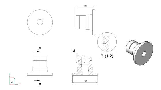
Build 3D components from existing 2D DWG data in a single environment. Use 3D solid geometry to generate detailed production data to interrogate hidden details within the model.

Import supplier data directly
Collaborate with suppliers using the ability to open DWG, Acis Sat (.sat), Rhino® (.3dm), Sketchup (.skp), and Wavefront (.obj) and edit directly in BricsCAD.
Hybrid 3D CAD modeling approach
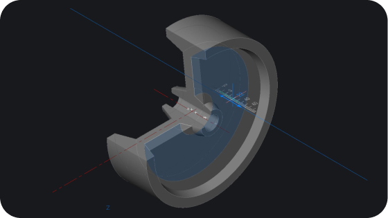
Combine parametric feature-based design and direct modeling to a 3D model in a single-part environment. This provides a flexible approach to producing concepts quickly in early designs.

Export CAD files for 3D Printing
Export 3D model data as an STL file to 3D software for additive manufacturing.
Visualize projects in a single platform
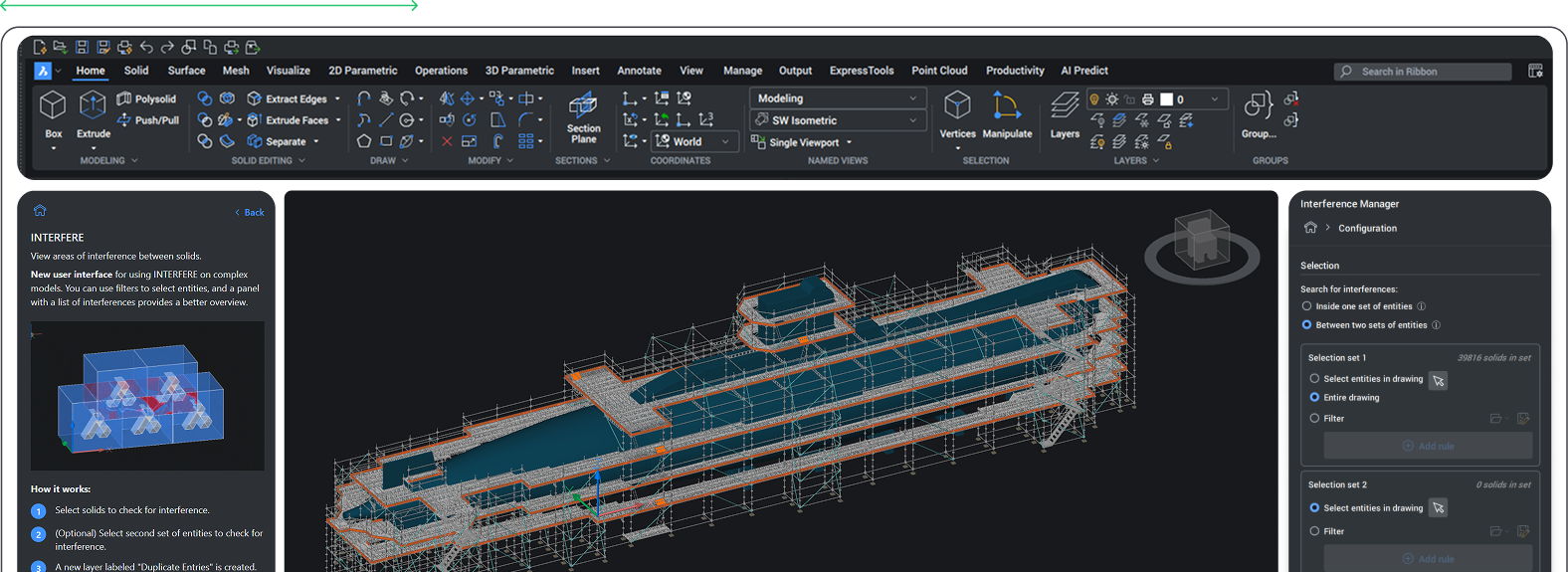
Plan in 2D to visualize in 3D on a single CAD platform: import 2D layouts and create 3D geometry to check interferences and clearances in real-time.
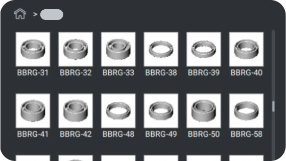
Industry-standard component library
Select from BricsCAD’s comprehensive library of standard components, saving time with ready-made supplier parts.
All BricsCAD Toolsets
Discover all BricsCAD Toolsets

30 day trial
Start designing in BricsCAD today!
